

All geometries
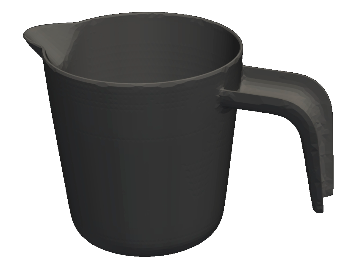
Measuring Cup
This is an everyday reference geometry with a familiar function and an overall axis-symmetric shape. Its key characteristic is a deliberate slight asymmetry caused by the spout and handle region. These local features can bias flow progression while the general geometry remains close to rotational symmetry.
Part Context & Geometry
The geometry was not included in the training data, making it a useful case to explore solver behaviour on an almost-symmetric part with localised functional features. This part is also intended as a shared benchmark, allowing users to simulate it in their own tools and directly compare results.
Suggested Experiments
Starter Setup: Inject at the centre of the bottom. Use PP with automatically selected default melt and mould temperatures.
Test A – Asymmetry Sensitivity (Single Gate): Switch to the alternative injection point (off-centre) and compare KPI values and the filling pattern.
Key Effect to Verify: Small geometric asymmetries (spout/handle) can measurably influence flow balance and end-of-fill location; gate position can reduce or amplify this effect.
Test B – Weld Line Steering (Two Gates): Activate two injection points and vary their locations. Observe where flow fronts merge (implicit weld line indication) and how KPI values change.
Key Effect to Verify: Multi-gate layouts provide control over where flow fronts meet, enabling weld lines to be shifted away from functionally sensitive regions.
Known Limitations: Freeze-related effects near the filling limit are not yet fully validated and are part of ongoing model refinement.
License: CC BY 4.0 – gpz3d via Fab.com. For details download zip file.
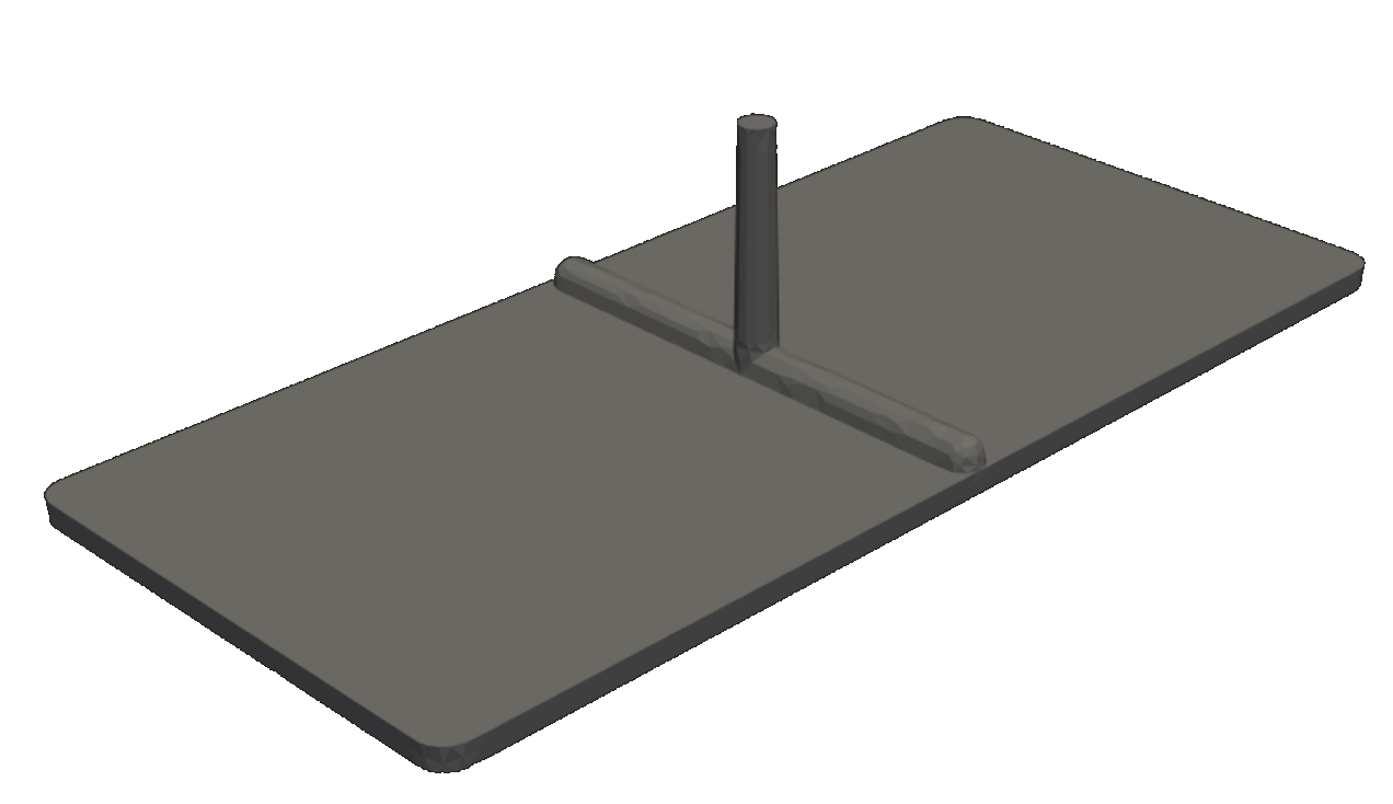
Plane Plate
This test plate is a standard benchmark geometry used across multiple internal projects. It is a simple, fully symmetric part designed to provide a clean reference case with minimal geometric complexity.
Part Context & Geometry
With the injection point located in the centre, the plate enables a highly controlled parallel flow front progression. This makes it ideal for evaluating basic solver behaviour such as symmetry, flow front stability, and general pressure trends without interference from ribs, thickness transitions, or flow obstacles. This part serves as a baseline reference to isolate material and process effects from geometric influences. It was not included in the model's training data.
Suggested Experiments
Starter Setup: Inject via the cold runner. Use any material with automatically selected default melt and mould temperatures.
Test A – Material Sensitivity: Switch between different materials while keeping process settings constant. Compare the KPI table results, especially maximum pressure and fill time.
Key Effect to Verify: The filling pattern remains stable due to the symmetric geometry, while pressure levels change significantly depending on viscosity and material behaviour.
Test B – Process Sensitivity: Adjust melt temperature and injection speed within the slider ranges. Compare KPI changes.
Key Effect to Verify: Process settings mainly influence KPI values (pressure and fill time), while the symmetric parallel filling behaviour remains largely unchanged.
Known Limitations: No specific limitations are expected for this geometry. It serves as a reference case for solver consistency and KPI trends.
Vacuum Sensor
This part originates from the automotive sector and is a standard reference geometry used on our instrumented injection moulding test machine to correlate simulation results with real-world measurement data.
Part Context & Geometry
The geometry is more complex than the previous examples, combining dome-shaped regions, flat plates, and reinforcing ribs in a compact layout. These interacting features create multiple merging flow fronts, making weld line formation a functionally relevant topic. The part was not included in the AI solver training data, making it well-suited to evaluate solver behaviour on unseen, production-like geometries.
Suggested Experiments
Starter Setup: Use ABS. Apply the original injection point on the long side of the part, opposite the tube hose, with default process parameters. Observe the filling pattern and the resulting weld line locations, which are typically critical for mechanical strength.
Test A – Gate Position Influence: Move the injection point to alternative locations and observe how weld lines shift within the part.
Key Effect to Verify: Weld line positions can be actively influenced and moved into less critical regions through gate placement.
Test B – Multi-Gate Layout: Activate a second injection point and vary both gate locations. Observe how flow front interaction changes the number, position, and orientation of weld lines.
Key Effect to Verify: Multi-gate concepts provide additional degrees of freedom for weld line control.
Known Limitations: In some cases, the solver may indicate flow connections across very small gaps, particularly near clip features. This behaviour is part of ongoing refinement to further improve geometric robustness.
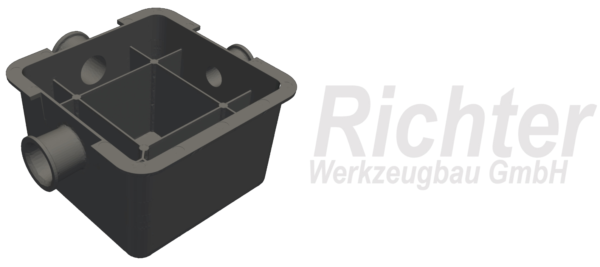
Pump Housing
This geometry originates from a real customer application (Richter Werkzeugbau GmbH) and was intentionally excluded from the AI solver’s training set, making it an excellent benchmark for evaluating the model's generalisation capabilities.
Part Context & Geometry
The design represents a widely used injection-moulded concept: a housing-like box structure reinforced by internal ribs. While this specific part is a pump housing, similar rib-supported housings are common across various technical applications. The part features pronounced wall thickness transitions between the outer walls, thin ribs, and locally thickened rib junctions. These variations create significant differences in local flow resistance and melt velocity, resulting in a characteristic non-uniform filling behaviour.
Suggested Experiments
Starter Setup: Inject at the centre of the top deck. Use ABS Generic with automatically selected default melt and mould temperatures.
Test A – Process Sensitivity: Vary melt temperature and injection speed within the slider ranges. Use the KPI table to compare maximum pressure and fill time.
Key Effect to Verify: Process changes primarily affect KPI levels, while the dominant flow path remains stable. Faster injection does not always lead to higher pressure; material heat-up and higher speed both influence pressure losses, often revealing a pressure minimum.
Test B – Gate Sensitivity: Switch to the alternative injection point (e.g., on an inner rib). Compare KPIs and observe changes in flow directions and rib filling sequence, including delayed or stagnating rib filling.
Key Effect to Verify: Gate location significantly impacts flow balance and local filling behaviour.
Known Limitations: The solver may exhibit freezing effects in thin ribs when the flow front slows down. This behaviour is not yet fully validated and is currently under investigation for improvement.
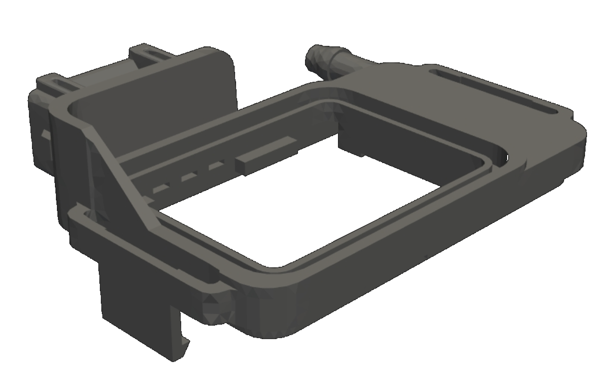
Rectangular Clip
This is a fictitious reference geometry designed specifically to explore flow termination and balance effects. The part features multiple end-of-fill regions, making it highly sensitive to gate location and flow symmetry.
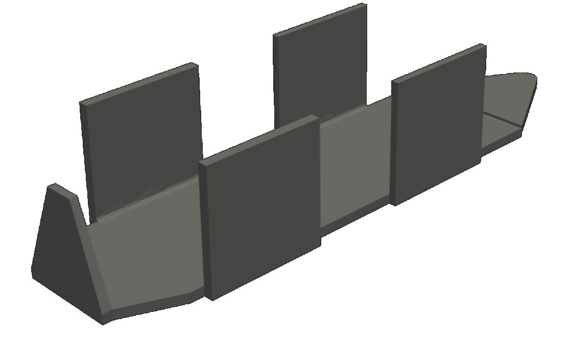
Part Context & Geometry
The geometry is largely defined by uniform wall thickness, which minimises thickness-driven flow effects and places the focus on flow path length and symmetry. It is symmetric along one axis, while the thickness of the sides changes between sections. Depending on the injection point, symmetric filling on both sides can be achieved. As it was not part of the training data, it is suitable for evaluating generalisation. Similar flow situations are common in clips, snap-fits, and bracket-like components.
Suggested Experiments
Starter Setup: Inject at the bent end at the top of the part using PP and default process parameters. The intended result is a symmetric left/right filling pattern, with the end of filling located at the opposite edge.
Test A – Gate Position Influence: Move the injection point to alternative locations. Observe how the end-of-fill position shifts and how flow front symmetry changes.
Key Effect to Verify: Gate location directly controls flow balance and the position of last-to-fill regions.
Test B – Multi-Gate Balancing: Activate two injection points and vary their positions. Observe how a more balanced filling can be achieved across all end-of-fill regions.
Key Effect to Verify: Multi-gate layouts can be used to equalise flow lengths and synchronise multiple flow endings.
Known Limitations: In unbalanced filling scenarios, pressure might be underestimated. This is under investigation.
Cap
This is a small, everyday reference part with a well-known function. Despite its simple appearance, the cap contains fine features, including an internal thread and structured outer surfaces.
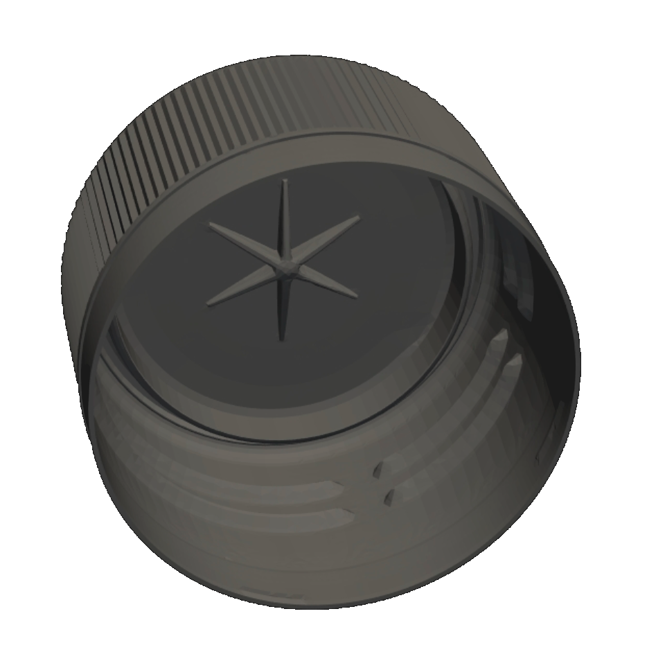
Part Context & Geometry
These small geometric details typically require a very fine mesh in conventional simulations, leading to longer computation times. The part is therefore well-suited to demonstrate solver behaviour on feature-rich, small-scale geometries. The geometry was not included in the AI solver training data, making it another relevant case for evaluating generalisation.
Suggested Experiments
Starter Setup: Use HDPE. Inject at the centre of the part with default process parameters to achieve symmetric circumferential filling.
Test A – Process Window Limits: Vary injection speed and melt temperature within the slider ranges. Observe how complete filling is not always achieved and how the KPI values change near the process limits.
Key Effect to Verify: Small feature sizes create high flow resistance and narrow the usable process window.
Test B – Gate Position Sensitivity: Move the injection point away from the centre. Observe how quickly filling symmetry is lost and how the end-of-fill location shifts around the circumference.
Key Effect to Verify: Circumferential flow in caps is highly sensitive to gate position, strongly influencing balance and end-of-fill behaviour.
Known Limitations: Freeze-related effects near the filling limit are not yet fully validated and are part of ongoing model refinement.
Megaphone
This geometry represents a cone-like part with a handle connected at two locations. The main body is close to axis-symmetric, while the handle attachments introduce local flow constraints and additional merging/splitting of flow fronts.
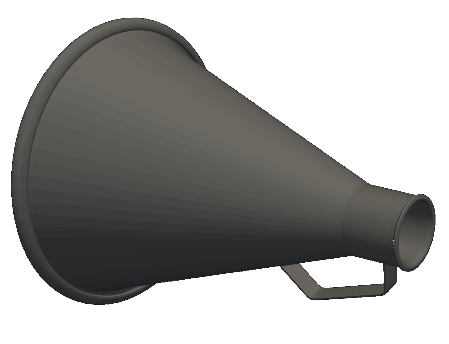
Part Context & Geometry
The part is well-suited to study how a secondary feature (handle) influences circumferential flow balance and end-of-fill behaviour. Although the part is not optimised for ejection due to undercuts, it represents common injection moulding geometries well. As with all demo geometries, it was not included in the AI solver training data.
Suggested Experiments
Starter Setup: Inject at the upper edge of the small opening (centre injection is not possible). Use default process parameters and a standard material.
Test A – Circumferential Flow Control (One vs. Two Gates): Switch between one and two injection points and rotate the gate position around the circumference. Compare KPIs and observe how the filling balance and end-of-fill location shift.
Key Effect to Verify: Gate positioning strongly controls circumferential flow progression in cone-like parts.
Test B – Handle-Driven Weld Line Positioning: Place one injection point on the handle region and move it around the handle attachment areas. Observe where the flow fronts meet and how the weld line location changes.
Key Effect to Verify: The handle attachments act as dominant flow constraints and can be used to intentionally shift weld lines into more favourable regions.
Known Limitations: In some cases, the solver may show non-physical connections across small gaps near the end of the megaphone, which can lead to unrealistic flow bridging. This behaviour is under investigation.
Square Basin
This is an everyday reference part representing a typical open container geometry with rounded corners and largely uniform wall thickness. The symmetric layout makes it an ideal case to study balanced filling and controlled flow front merging.
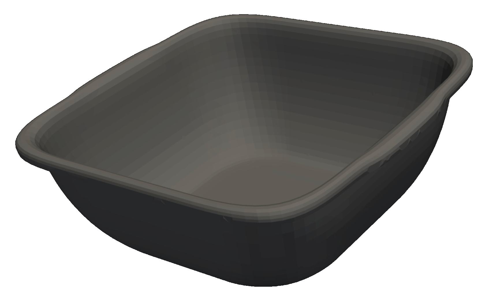
Part Context & Geometry
Despite its simple appearance, the square shape naturally creates competing flow paths toward the corners, making weld line positioning and end-of-fill balance highly sensitive to gate placement. As with all demo geometries, the part was not included in the AI solver training data.
Suggested Experiments
Starter Setup: Inject at the centre of the bottom. Use PP with automatically selected default process parameters. Observe the symmetric filling pattern and where flow fronts merge.
Test A – Weld Line and Balance Optimisation (Two Gates): Activate a second injection point and move both gates to achieve balanced filling, aiming for a setup where the weld line is located in the centre and the basin fills symmetrically. Balanced filling means the four corner regions reach end-of-fill at nearly the same time.
Key Effect to Verify: Gate positioning can be used to intentionally control weld line placement and end-of-fill symmetry.
Test B – Robustness Check (Material and Process Influence): Keep the optimised gate setup and switch to a different material. Observe whether the same gate concept still delivers balanced filling. Then, vary process parameters to evaluate if balance can be recovered.
Key Effect to Verify: A gate concept optimised for one material and process does not automatically transfer to others, highlighting the combined influence of material behaviour and process conditions.