


All features
Anticipating Interactions in Multi-Component Injection Molding
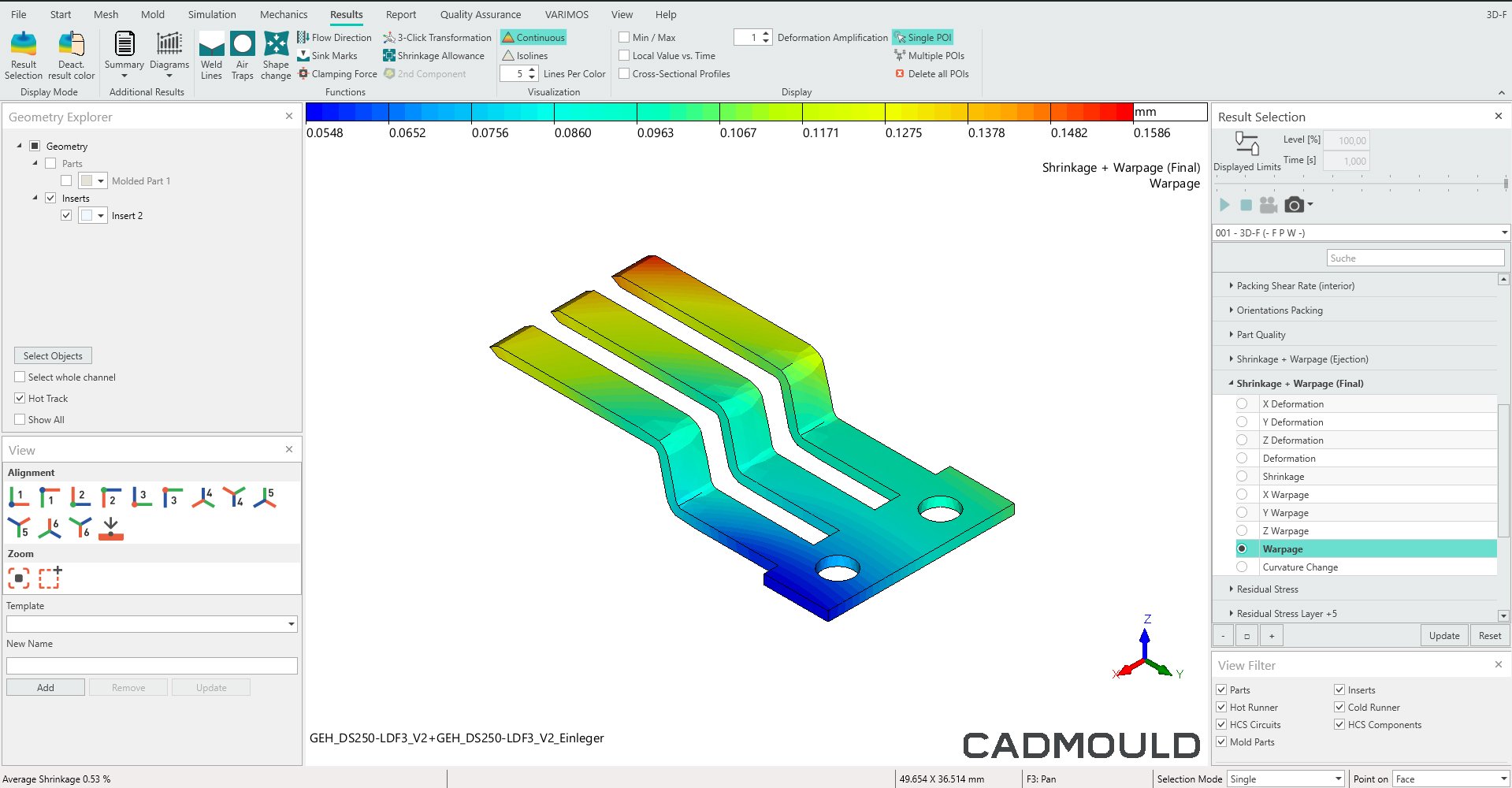
When multiple materials are combined into one part, complex interactions—like thermal and mechanical coupling during filling—are inevitable. These can lead to issues such as warpage and insert deformation.
If these effects aren’t addressed early, costly defects can arise. So, how can they be reliably predicted?
2K & Insert simulates the complex interactions between materials that occur when working with multiple plastic mold components, especially when inserts or multiple polymers are involved.
Instead of fixing unwanted effects after they happen, 2K & Insert helps you predict and proactively prevent them.
Benefits
- Improve part quality by analyzing and reducing shrinkage, warpage, and defects in multi-component molding
- Accurately predict core shift by identifying insert displacement caused by melt pressure during injection
- Fine-tune the injection process by adjusting gating, pressure, and mold design to minimize deformation
- Seamlessly integrate with Fill, Pack, and Warp, other features in the Cadmould ecosystem of injection molding simulation software, for full-process simulation
- Optimize insert pre-heating and cooling in molded components

How It Works
In injection molding for multi-component parts, pre-existing inserts or previously molded components introduce new boundary conditions within the cavity.
These elements, along with their thermal and mechanical behavior, influence cooling and material stresses. They affect the filling, packing, cooling, and deformation of the final product.
To make matters worse, the inserts themselves are exposed to melt pressure and thermal effects, further impacting part quality.
To help you address problems before they occur, 2K and Insert simulates these phenomena using a structured process:
- Modeling injection pressure and thermal effects: The software accurately simulates filling behavior, melt pressure distribution, and thermal conditions during overmolding, taking inserts into account.
- Simulating insert deformation: Advanced finite element methods (FEM) are used to predict how an insert will move, deform, or rotate under force.
- Deformation analysis: Results from the previous simulation steps inform the analysis of a part’s deformation behavior.
- Process optimization: You can adjust mold design, injection pressure, gating strategy, and cooling settings to minimize injection pressure and prevent excessive deformation.
Key Functionalities
Core Shift and Insert Deformation Analysis
2K & Insert simulates mechanical deformation through insert movement caused by melt pressure, using data from the stress-strain curve. This helps identify assembly misalignments or insert displacements that could lead to defects.
Multi-Material Interaction Simulation
Tools like FEM structural analysis and the stress-strain curve are used to evaluate how different materials (such as thermoplastics and metal inserts) respond to thermal and mechanical loads during overmolding.
Seamless Integration With Warp for Shrinkage and Warpage Simulation
With just one click, results can be automatically transferred to Warp, another feature in the Cadmould ecosystem, enabling advanced analysis of post-molding shrinkage and dimensional stability.
Process Optimization for 2K & Insert Moulding
Perform data-driven optimization of gating strategies, packing pressure, and cooling parameters, resulting in defect-free multi-component parts.
Industry
Cadmould 2K & Insert is an injection molding simulation software feature for manufacturers working with multi-material or insert molding processes. It has broad applications across industries, including:
- Automotive & Aerospace: Multi-material processes are used to produce precision-molded hybrid parts, structural reinforcements, and lightweight assemblies.
- Medical & Electronics: Insert molding is required to make metal-plastic connectors, casings, and overmolded micro-components.
- Consumer Goods & Industrial Equipment: Manufacturers rely on multi-component and insert molding techniques to produce multi-material housings, overmolded grips, and reinforced plastic-metal interfaces.
Engineers and simulation specialists use 2K & Insert to simulate multi-material interactions and core shift in plastic injection mold components. Simulation insights help them achieve higher dimensional accuracy, reduced defects, and optimized cycle times.
Integration & Compatibility
2K & Insert is a Cadmould feature. It integrates seamlessly with other products in the Cadmould ecosystem of injection molding simulation software to ensure accurate and efficient workflows.
Use it with other Cadmould features including:
2K & Insert is available with the Flex Advanced, Flex Premium and Flex Enterprise subscription plans or as an add-on.
3D-F

Balancing Speed and Accuracy in Injection Molding
Simulation for injection molding often involves a tricky trade-off between speed and accuracy. Traditional midplane models lack volumetric precision, while full 3D volumetric models are slow, rigid, and require expert-level setup. For parts with complex shapes or varying wall thicknesses, the former approach falls short on accuracy, while the latter consumes valuable time in setup and computation.
The 3D-F algorithm behind Cadmould eliminates this trade-off by combining the best of both worlds. It provides the high-resolution accuracy of volumetric models with the ease and speed of midplane approaches. 3D-F achieves this through an intelligent 3D Framework mesh that dynamically adapts resolution based on part geometry and process conditions—all without sacrificing computational speed. It enables ultra-fast, robust, and highly accurate simulations across most plastic parts, even the tricky ones.
Benefits
-
Achieve an excellent balance between speed and accuracy
-
Take advantage of automatic meshing for complex geometries
-
Analyze volumetric effects such as shrinkage and warpage
-
Count on high reliability for varying wall thicknesses
-
Get support for quick, iterative optimization workflows
-
Make parametric geometry changes without using CAD
How It Works
The 3D-F algorithm represents a next-gen category of simulation mesh—a 3D Framework—that eliminates the weaknesses and bottlenecks of traditional midplane and volumetric approaches. Instead of meshing the entire part interior with millions of finite elements, as in 3D volumetric models, 3D-F—the simulation algorithm behind Cadmould—starts with a surface mesh and enriches it with a scaffold of internal "tubes." These tubes act as intelligent paths to track material behavior and forces.
Across every part area, Cadmould dynamically distributes 25 integration points throughout the wall thickness, adjusting their locations in real time to focus computational effort where it matters most. Early in the filling stage, resolution is concentrated near the mold wall, where shear is highest. Over the course of the freezing process, maximum resolution continuously shifts to the evolving melt-solid boundary. This dynamic redistribution delivers ultra-high resolution while avoiding the slowdowns of 3D-V models.
Because 3D-F understands wall thickness as a native concept, geometry adjustments (like wall thickness variations) can be defined and optimized directly in Cadmould without needing to return to CAD.
Key Functionalities
Dynamic resolution optimization
The 3D-F algorithm adjusts the location of its high-resolution zones in real-time, based on key process variables like shear rate and temperature gradients. This dynamic approach provides exceptional accuracy while avoiding unnecessary computations.
Wall-thickness-aware geometry modeling
Unlike traditional 3D-V meshes, 3D-F inherently understands wall thickness. Users can adjust and optimize wall geometry directly in the simulation—perfect for parameter studies or automated optimization.
Ultra-fast meshing and simulation
With 3D-F, meshing is automated and streamlined, even for complex geometries. Additionally, because 3D-F is lightweight and efficient, it allows multiple simulations to run in parallel on standard hardware—ideal for design of experiments (DoE) and robust optimization.
Industry
3D-F is designed to handle the types of parts engineers actually work with—not simplified textbook models, but real-world components with non-uniform wall thicknesses, functional features (like ribs, domes, and seals), and asymmetric geometries.
This makes 3D-F highly versatile across industries like electronics, medical devices, and household goods. Automotive interior design is another major application—where parts such as airbag housings or clips often feature sharp transitions and variable wall thicknesses, which are challenging or inefficient to simulate with midplane or 3D-V models.
The superior balance of accuracy and speed offered by 3D-F shines not only in single simulations but especially when exploring multiple design and process variations. By pairing 3D-F with Varimos, the AI assistant for Cadmould, users can automatically explore extensive design options and quickly arrive at robust, high-performance solutions.
Integration & Compatibility
3D-F was designed for the Cadmould ecosystem. It’s built directly into Cadmould and comes standard with the Flex Basic, Flex Advanced, Flex Premium, and Flex Enterprise subscription plans. It’s the default simulation engine for key workflows like filling, packing, shrinkage, and warpage simulations.
Key features of 3D-F include:
- Full compatibility with Varimos, the Cadmould AI assistant, for automation, DoE, and optimization workflows.
- No need for special hardware—its efficient architecture runs smoothly on standard CPU-based systems.
- Support for importing CAD files in common formats, with automated meshing to reduce manual work.
- An internal data structure that integrates effortlessly with post-processing tools for advanced visualization and reporting.

Closing the Simulation-to-Visualization Gap
Surface defects can significantly affect the perceived quality of plastic parts, especially in industries where design is critical. Traditional simulation outputs, however, are often too abstract for stakeholders to accurately predict how the surface texture will look. This disconnect can result in expensive changes later on.
Authentic Surface Graining bridges the gap between abstract simulation data and real-world appearance. Instead of interpreting complex shrinkage plots or deformation vectors, users get a photorealistic rendering of their part—complete with surface texture and deformations—exactly as it would appear under real-world lighting.
Benefits
- Accurately simulate part appearance under real-world lighting
- Visually identify final part surface defects before production starts
- Compare grain options side-by-side to take the guesswork out of trade-off decisions
- Enhance communication across teams and with clients with clear visual outputs that eliminate subjective interpretation
- Minimize the risk of expensive mold modifications after production begins
How It Works
Authentic Surface Graining incorporates 3D CAD design along with key technical data—like material selection, cooling conditions, shrinkage, and packing pressure—and transforms them into clear visual outputs.
Results are displayed live in a dedicated rendering window, enabling side-by-side comparisons of options. Whether during design reviews, tooling discussions, or customer presentations, users can quickly evaluate a part's visual quality—no in-depth simulation expertise needed.
Key Functionalities
Visualizing Textured Simulation Results
With photorealistic surface rendering, project managers and decision-makers can make faster, more confident choices. By importing a part’s 3D CAD design and texture file into Cadmould, Authentic Surface Graining goes beyond standard calculations to preview the part as it would appear in real life—including texture, lighting effects, and simulated surface imperfections like sink marks.
Side-by-Side Grain Comparison
In a dedicated rendering window, Authentic Surface Graining lets you view and compare different grain options for a designed part side by side. You can virtually "pick up," rotate, and inspect the part to see which option best hides flaws.
Scalable Visualization of Deformation
Easily scale shrinkage and warpage effects to thoroughly evaluate how deformation impacts the part.
Custom Mesh Integration
Authentic Surface Graining renders results directly on user-provided meshes, allowing you to accurately assess how your part’s texture interacts with deformation data.
Industry
From choosing materials to conducting virtual design reviews, Authentic Surface Graining allows for fast, visual validation that’s clear to everyone involved—even stakeholders without a technical background.
Roles that benefit from using Authentic Surface Graining include:
- Automotive interior designers & simulation engineers: In automotive manufacturing, Authentic Surface Graining helps visualize dashboards, door panels, and other high-visibility parts to ensure that grain selection effectively masks potential sink marks.
- Consumer electronics designers: For sleek components like phone backs or wearable housings, designers can verify that fine-grain textures won’t reveal defects.
- Toolmakers & mold designers: Technical stakeholders can easily demonstrate to clients how different cooling setups or materials will affect visible surface quality—without the need to interpret complex shrinkage plots or heat maps.
- Project managers & decision-makers: Non-technical stakeholders get the insights they need to make quick, informed approvals.
Integration & Compatibility
Authentic Surface Graining:
- seamlessly integrates with the Cadmould ecosystem of injection molding simulation software, using numerical simulation data (e.g., cooling simulation results and shrinkage & warpage analysis) to produce its output;
- works with user-provided textured meshes and allows for multiple mesh variants to be compared;
- offers photorealistic previews in a standalone rendering window, enabling parallel workflows; and
- supports common 3D CAD design formats and textures used in automotive and consumer electronics applications.
Authentic Surface Graining is available with the Flex Enterprise subscription plan or as an add-on.
Batch

Maximizing Efficiency in Multi-Simulation Workflows
Simulation workflows often demand multiple test cases with different parameters. Without automation, these simulations have to be run manually, which is both time-consuming and error-prone.
Batch eliminates the need for manual intervention by automating your multi-simulation workflow. You don’t have to wait for one simulation to finish before starting the next—its intuitive interface allows you to effortlessly set up an automated queue.
Benefits
- Easily manage tasks with simple queueing and prioritization of injection molding simulation variants for organized execution
- Boost efficiency with uninterrupted processing of multiple simulations in a row, cutting down on the need for manual input
- Reduce errors with accurate, reliable execution of all queued simulations
- Enhance productivity by allowing engineers to spend more time analyzing results and making decisions

How It Works
Batch makes it easy to set up multiple simulation scenarios and run them automatically for maximum efficiency and accuracy.
As a user, you can prepare injection molding simulation variants for virtual analysis, add them to a task list, and prioritize their execution order based on project needs. Once the queue is triggered, the system processes each simulation sequentially without interruption—no need for manual oversight. While the simulations run in the background, engineers can focus on more critical tasks.
When the simulations are complete, results are automatically saved and organized for easy analysis. Outcomes for different simulation variants are displayed side-by-side, helping you quickly identify the best design and process parameters. This saves time, enhances the reliability and consistency of simulation workflows, and empowers you to make informed decisions without the delays of manual execution.
Key Functionalities
Automated Multi-Simulation Execution
Batch automates the sequential execution of multiple injection molding simulations, eliminating the need for manual oversight. Once added to the task list, simulations are processed in the pre-defined order. This uninterrupted execution allows engineers to focus on analyzing results and driving innovation.
Intuitive Task Management
Managing and prioritizing simulation variants is simple with a user-friendly interface designed for efficient project execution. The pre-defined execution list reduces errors and streamlines complex simulation workflows, saving time and resources.
Seamless Organization of Results
Batch automatically saves and organizes simulation results in one centralized location. With side-by-side comparisons of different simulation variants, you can quickly identify the best design and process parameters. Decision-making is faster, and outcomes are consistent at every stage of the workflow.
Error Reduction Through Automation
By automating processes, Batch minimizes errors caused by manual execution. The system ensures each simulation is executed with precision, delivering consistently high-quality results and improving reliability across workflows.

Industry
Batch is an essential tool for streamlining simulation workflows and improving efficiency across industries, including:
- Automotive manufacturing, where injection molding is used to produce components like dashboards and bumper systems.
- Aerospace, which depends on high-performance injection-molded parts such as turbine housings and structural brackets.
- Medical device manufacturing, where the Cadmould simulation ecosystem ensures that precision-molded parts like surgical instruments and implant casings meet the highest quality and regulatory standards.
- Electronics and industrial equipment manufacturing, where Batch is used to evaluate material options for components ranging from connectors and cooling housings to pump casings and precision gears.
No matter the industry, the automation capabilities of Cadmould Batch help reduce errors and accelerate the production of high-quality products, bringing them to market faster and more efficiently.
Integration & Compatibility
Batch seamlessly integrates with other features in the Cadmould ecosystem of injection molding simulation software to enable end-to-end simulation. When combined with Fill, Pack, and Warp, it allows you to efficiently analyze molding parameters across various stages using powerful batch processing capabilities.
Batch is also compatible with Varimos AI, the AI assistant for the Cadmould ecosystem. Varimos leverages machine learning based on simulation data to quickly identify optimal parameter combinations. Batch supports parallel execution on multiple processors for improved efficiency (multi-core processing).
Batch is included in the Flex Advanced, Flex Premium, and Flex Enterprise subscription plans.
Cascadic Injection

Mastering Filling in Multi-Gated Molds
Multiple gates are opened and closed during cascade injection molding in hot runner systems. Without simulation software to optimize the opening and closing sequences, defects like weld lines, pressure drops, air entrapment, and uneven shrinkage can occur.
Cascadic Injection is an advanced feature designed to tackle the challenges of multi-gate molding. It allows you to simulate and optimize gate-switching sequences during the injection process. This results in more uniform filling, improved part quality, and fewer defects.
Benefits
- Optimize filling for large, multi-gate components
- Reduce defects by ensuring even material distribution
- Accurately control gate opening timing and adjust sequencing to eliminate weak weld lines
- Reduce injection pressure and warpage defects from injection molding while managing fiber orientation to minimize areas of mechanical weakness
- Improved defect prevention: Detect and fix air entrapment, pressure drops, and flow imbalances
- Faster process optimization: Quickly and interactively compare multiple gating strategies to find the best solution

How It Works
Cascadic Injection allows you to simulate and optimize gate switching sequences through a clear, structured workflow.
- Before: In the setup phase, you define gate locations and timing strategies for opening and closing. Each gate can be individually controlled based on specific events, such as cycle time, flow front position, or local pressure.
- During: In the simulation phase, Cascadic Injection dynamically models filling behavior as gates open, close, and reopen at preset moments or triggers. The simulation software provides a detailed view of material flow changes, weld line formation, pressure distribution, and air entrapment during each stage of the cascade injection molding process in a hot runner system.
- After: Using the simulation data, you can fine-tune gate timing and injection parameters to optimize weld line location, reduce pressure peaks, and enhance cooling balance. These efficient, data-driven adjustments help ensure better structural integrity and visual quality of the final parts.
Key Functionalities
Precise Control of Gate Opening Sequences
Cascadic Injection allows you to simulate how different gate opening and closing sequences impact filling patterns, weld line locations, and pressure balancing. With this data, you can fine-tune timing and filling parameters to achieve optimal mechanical properties.
Weld Line Elimination and Flow Optimization
Fiber orientation plays a crucial role in the mechanical strength of weld lines. By analyzing how a proposed gate opening sequence affects fiber orientation, you can strengthen weld lines or even eliminate them entirely—key steps in the injection molding validation process.
Integrated Analysis of Shrinkage, Cooling, and Warpage Defects in Injection Molding
Seamless integration with Pack and Cool—other features in the Cadmould ecosystem—enables you to simulate how gate sequencing affects shrinkage, cooling rates, and final part deformation. These insights help minimize warpage and improve dimensional stability during cascade injection molding in hot runner systems.
Injection Pressure Optimization
Cascadic Injection predicts the maximum injection pressure needed for a gate switching schedule and identifies ways to reduce excessive pressure through targeted adjustments. The result: less machine wear and lower energy consumption.
Visualization of Flow Behavior and Air Entrapment
Cascadic Injection provides animated visualizations of flow fronts, weld lines, air pockets, and pressure zones. This advanced flow simulation feature helps you identify and address potential issues—like venting problems or short shots—before they arise.
Industry
Cascadic Injection is a key process optimization tool for industries that require multi-gate injection molding to produce large, complex parts. It ensures high strength, precise dimensions, flawless surface quality, and other critical requirements on the injection molding validation checklist.
Industries that benefit from Cascadic Injection include:
- Automotive and aerospace manufacturing: Cascadic Injection helps create bumpers, dashboards, and structural components with optimized weld line placement and reduced warpage.
- Medical and electronics manufacturing: Cascadic Injection provides precise control over flow sequencing, ensuring high surface quality and fewer defects in thin-walled precision components.
- Industrial equipment and consumer goods: By optimizing sequential valve gating, Cascadic Injection prevents overpacking and reduces pressure fluctuations. The result is stronger, more durable plastic parts with consistent mechanical properties.
Integration & Compatibility
Cascadic Injection is a Cadmould feature that works seamlessly with other tools in the Cadmould system.
Pair it with:
Cascadic Injection is available in the Flex Basic, Flex Advanced, Flex Premium, and Flex Enterprise subscription plans.
Fiber

Controlling the Effects of Fiber Flow on Part Quality
Fiber-reinforced plastic (FRP) exhibits anisotropic behavior, meaning its stiffness and strength depend on how the fibers align during injection molding. Poor alignment can cause uneven or directional shrinkage, leading to warping and reduced part quality. So, how can this be avoided?
Fiber has the solution. It precisely simulates fiber orientation during injection molding, enabling informed, data-driven optimization. By understanding flow behavior, you can adjust mold design and process settings to improve part quality and mechanical stability.
Benefits
- Accurately simulate fiber orientation in fiber-reinforced plastic parts to understand anisotropic behavior
- Use insights from fiber alignment analysis to improve part stability and mechanical properties
- Seamlessly integrate with Cadmould Warp to model warpage effects and achieve better warpage control in parts with anisotropic materials
- Optimize gating strategies to improve fiber distribution and minimize defects
- Accelerate design iterations and reduce costly trial-and-error by simulating and refining fiber flow during molding
- Combine with Fiber Export, an add-on in the Cadmould ecosystem of injection molding simulation software, to easily transfer fiber orientation simulation data to structural solvers
How It Works
Fiber is a fiber orientation simulation feature in the Cadmould ecosystem of injection molding simulation software. It predicts how fibers will align during injection molding based on flow direction and process parameters, taking into account injection speed, gate locations, and cooling effects to generate a detailed fiber orientation tensor field. This helps you understand how shrinkage and warpage are influenced by flow-induced fiber orientation under specific process conditions.
Controlling this fiber-induced shrinkage and warpage is critical for achieving dimensional stability. Since shrinkage in anisotropic materials depends on fiber orientation, Fiber works seamlessly with Warp, another feature in the Cadmould family, to reflect this dependency. Together, Fiber and Warp provide an integrated approach to accurately predict final part deformation.
These insights allow you to proactively minimize warpage effects by optimizing process conditions and mold design. Adjustments to gating locations, processing temperatures, and material flow paths can improve fiber alignment, reducing the risk of defects such as weak points, stress concentrations, and dimensional inaccuracies. This ensures the quality of the final part is optimized before physical production even begins.
Key Functionalities
Accurate simulation of fiber orientation
Enter the gate locations and other molding parameters, and Fiber accurately predicts fiber alignment and distribution based on the specified parameter set.
Impact of fiber orientation on mechanical properties
Rather than assuming isotropic behavior, Fiber allows you to accurately predict shrinkage, warpage, and structural performance of a part based on actual flow-induced fiber orientation.
Seamless integration with Warp for enhanced warpage simulation
Fiber integrates seamlessly with Warp, a sophisticated warpage simulation feature in the Cadmould ecosystem. Warp analyzes fiber orientation simulation data from Fiber to determine anisotropic shrinkage effects, improving predictions of dimensional stability.
Optimizing part and mold design with high-quality data
Fiber provides the data you need to refine gating strategies, mold design, and process parameters. Less guesswork, better part quality, and fewer defects.
Seamless export of data with Fiber Export
Fiber Export transfers fiber orientation simulation data from Fiber to external structural solvers for advanced FEA analysis. This enables seamless integration between Fiber and leading tools such as Abaqus, Ansys, and Nastran.
Please note that this export functionality is not included in Fiber itself. For more information on exporting fiber data, visit the Fiber Export page.
Integrated FEM based on fiber orientation data
Fiber can be combined with Part FEM, another feature in the Cadmould ecosystem, to deliver integrated FEM based on simulations of actual fiber orientation behavior.

Industry
Across industries, fiber orientation plays a critical role in determining the mechanical behavior, durability, and dimensional stability of fiber-reinforced injection-molded components.
Therefore, the ability to simulate fiber orientation in injection molding simulation software is essential for various high-performance applications, including:
- Automotive and aerospace manufacturing: Lightweighting strategies demand precise control over fiber alignment to achieve optimal strength-to-weight ratios and crash safety performance.
- Consumer electronics: Designs need to be impact-resistant and thin-walled.
- Medical devices: Sterile, high-precision components rely on stable fiber behavior.
- Industrial equipment and heavy machinery: Components must withstand high loads and resist fatigue over extended lifespans.
In these sectors and beyond, Fiber provides engineers and manufacturers with the tools to simulate, optimize, and validate fiber orientation effects, reducing trial-and-error costs and improving the reliability of fiber-reinforced plastic components.
Integration & Compatibility
Cadmould Fiber brings advanced fiber orientation simulation capabilities to the Cadmould injection molding software ecosystem. Use it seamlessly with the following Cadmould features:
Fiber is available in the Flex Basic, Flex Advanced, Flex Premium, and Flex Enterprise subscription plans.

High-Fidelity in Structural Simulations
Fiber-reinforced plastic (FRP) exhibits anisotropic behavior, meaning its stiffness, strength, and thermal expansion change depending on fiber orientation. However, standard structural simulations often assume isotropic properties, which can result in inaccurate predictions of stress distribution, deformation, and failure risks.
That’s where Fiber Export comes in. Anisotropic behavior requires structural simulations of FRP parts to use accurate, not assumed, fiber orientation data. With Fiber Export, seamless transfer of simulated fiber alignment data enables high-fidelity structural simulations.
Benefits
- Perform accurate mechanical simulations based on the realistic behavior of fiber-based materials
- Optimize part strength and weight with informed calculations in FEA tools
- Cut prototyping costs by validating real-world performance before physical development begins
- Improve thermal and warpage predictions for greater long-term durability of fiber-reinforced parts
- Benefit from seamless integration with popular FEA tools (Abaqus, Ansys, Nastran, etc.) for advanced analysis
How It Works
The Fiber Export workflow starts with Fiber, a feature in the Cadmould family that predicts the flow and orientation of fibers during the injection molding of fiber-reinforced plastics and other anisotropic materials. Fiber analyzes how factors like injection speed, gate placement, and material choice interact to determine overall filling behavior. This simulated filling behavior is then used to create a detailed fiber orientation tensor field.
Once the fiber orientation is accurately simulated for the fiber-reinforced molding component, Fiber Export seamlessly transfers this data to structural solvers. Files can be imported into leading tools either directly (such as with Ansys and Hypermesh) or using mapping software like Converse (for Nastran and Abaqus). Just as importantly, Fiber Export preserves flow-induced fiber orientation at a granular level, ensuring an accurate representation of material anisotropy in different regions of the part.
The next step involves using your chosen FEA simulation software to perform accurate structural simulations of how the product will perform in the real world. By integrating local fiber orientation information into the FEA process, the mechanical properties of each element are individually adjusted to reflect their anisotropic behavior.
Key Functionalities
Accurate predictions for fiber-based material behavior in fiber-reinforced plastic parts
Stop relying on simulations that ignore anisotropic material behaviors. With detailed fiber orientation data export, Fiber Export equips FEA simulation software with the precise information needed to accurately predict product stress and deformation. This enables more efficient product development based on material loads, fewer prototypes, and faster development cycles.
Seamless data export for structural analysis
Fiber Export takes fiber simulation data generated in Cadmould Fiber and creates fiber orientation tensor fields ready for export to leading structural solvers, either directly (Ansys, Hypermesh) or via mapping software like Converse (Nastran, Abaqus). This allows you to seamlessly integrate flow-induced fiber orientation data into your FEA workflow, ensuring faster development of FRP parts.
Optimized part and material design
Using real fiber orientation data, you can fine-tune fiber alignment in glass or carbon fiber-reinforced parts to enhance load-bearing performance exactly where it’s needed. This advanced optimization leads to better-performing parts while minimizing material consumption.
Improved thermal and warpage predictions
Fiber orientation plays a major role in how a part expands or contracts when exposed to heat. By incorporating real fiber orientation data into your FEA workflow, you’ll achieve more accurate predictions of stress distribution under various thermal and mechanical conditions. This gives you the insights needed to prevent deformation and ensure dimensional stability.
Industry
Fiber Export plays a key role in industries that depend on high-performance, fiber-reinforced plastic parts, where accurate predictions of mechanical and thermal behavior are critical.
Industries that benefit from Fiber Export include:
- Automotive and aerospace: Fiber Export supports the simulation of injection-molded parts with anisotropic properties, such as glass or carbon fiber-reinforced plastics. This ensures optimal strength and safety for structural components like battery housings, crash-resistant parts, and lightweight, load-bearing elements.
- Medical and electronics: Fiber Export improves the dimensional stability and mechanical reliability of precision-molded components, which are vital for functionality and durability.
- Industrial equipment: Fiber Export enables engineers to design gears, brackets, and reinforced parts that maximize strength and lifespan.
By integrating real-world fiber orientation data into FEA simulations for fiber-reinforced molding materials, manufacturers achieve more reliable designs, lower material costs, and faster development cycles. Fiber Export is an essential tool for advanced structural analysis across a wide range of high-tech industries.
Integration & Compatibility
Fiber Export integrates seamlessly with a variety of leading FEA and digital mapping tools, including:
- Abaqus
- Ansys
- Hypermesh
- Nastran (for advanced medical analysis)
- Digimat
- Converse
Fiber Export is available exclusively with the Flex Enterprise subscription plan or as an add-on.
Fill

Optimizing Filling Behavior for Part Quality
The flow of molten plastic into the mold cavity during injection molding plays a crucial role in determining a part’s quality and durability. Failing to analyze and optimize key process parameters like position, temperature, and pressure can lead to short fills, air traps, and poorly placed weld lines, often requiring expensive rework.
Fill is a powerful filling simulation software that accurately predicts mold filling behavior. Its detailed simulation data identifies flow-related issues early in the design phase, enabling you to optimize mold design, gate placement, and process parameters. By doing so, Fill helps reduce costly trial-and-error iterations later on.
Benefits
- Reduce maximum injection pressure and clamping force, and improve weld line location by strategically positioning the injection point
- Prevent common issues like air traps, unbalanced filling, and short shots in injection molding
- Optimize gate locations to ensure uniform filling and enhance part integrity
- Improve the balance of hot and cold runner systems
- Speed up development cycles and cut costs by reducing mold corrections and minimizing trial-and-error in physical testing

How It Works
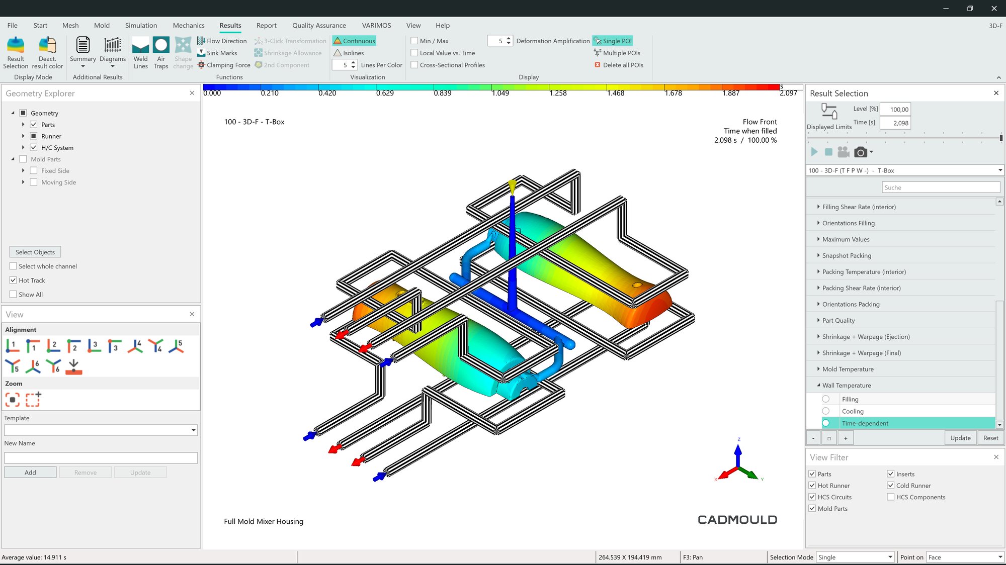
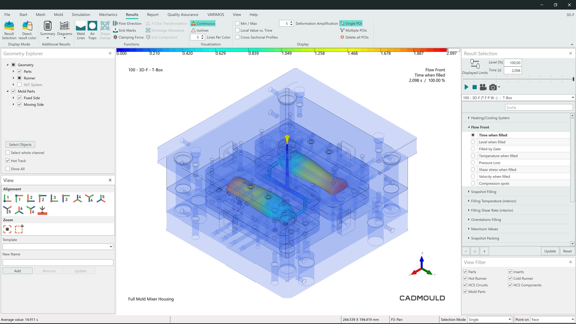
Fill analyzes the entire filling phase of the injection molding process, providing detailed insights into how the melt flows inside the mold. It uses advanced fluid flow modeling to predict melt dynamics, calculate fill time, and identify potential defect areas.
Key features of Fill include:
- Mold filling simulation with melt front visualization
- In-depth analysis of material pressure, temperature, and shear stress inside the mold
- Automatic gate placement optimization to shorten the maximum flow path
- Simulation of family and multi-cavity molds for complex part configurations
These tools help you identify and resolve potential issues before the first physical mold is even created.
Key Functionalities
Analysis of Mold Filling Behavior
Fill predicts melt front movement and accurately calculates injection molding fill time, helping you ensure even filling and avoid flow-related defects.
Gate and Runner Optimization
Proper gate placement and a balanced runner system are essential for controlling the flow of molten plastic into mold cavities. Fill provides insights to optimize gate locations and balance both hot and cold runner systems, ensuring uniform filling in single or multi-cavity molds.
Detection of Air Entrapment, Weld Lines, and Short Shots
Issues like air entrapment, weld lines, and short shots can weaken parts and impact their appearance. By simulating the mold filling process, Fill helps identify these problem areas during the design stage.
Process Parameter Tuning
With mold flow simulation, you can evaluate how variables like temperature and injection speed affect filling behavior. This allows you to fine-tune process parameters to achieve defect-free molding, even for complex filling profiles.

Industry
In various industries, achieving consistent, defect-free mold filling is critical for producing high-quality plastic components.
Industries that benefit from Fill include:
- Automotive & Aerospace: Filling simulation enhances the molding of lightweight automotive parts.
- Consumer Electronics: Understanding filling behavior ensures flawless molding of thin-walled electronic casings.
- Medical Device Manufacturing: Preventing defects through filling simulation helps meet strict regulatory standards for medical components.
For engineers working on real-world applications, Fill delivers the precision needed to refine designs before production. By simulating and optimizing the filling process, manufacturers can speed up development, reduce expensive mold iterations, and achieve superior product performance across diverse applications.
Integration & Compatibility
Fill integrates smoothly with other features in the Cadmould ecosystem of injection molding simulation software for complete end-to-end injection molding simulation.
Use it with:
Fill also offers a variety of export options, including:
- VMAP open CAE standard
- TopSolid Mold
- Creation of customizable HTML and PDF reports for easier documentation and collaboration
Fill is available through Flex Basic, Flex Advanced, Flex Premium, and Flex Enterprise subscription plans.

The Unique Challenges of Foam Injection Molding
Gas expansion, density variation, bubble formation, and complex flow behavior can cause sink marks, warping, and air inclusions in foamed parts. The challenge for injection molders is that standard simulation tools often fail to capture these complexities.
Foam Processing accurately models chemical and physical foaming processes like MuCell®, Cellmould®, and Optifoam®. It predicts bubble distribution, material density, and defect formation, helping you optimize lightweighting, shorten cycle times, and prevent defects before production even starts.
Benefits
- Predict density distribution and gas volume fraction changes with accurate foam expansion modeling
- Control foam behavior to optimize lightweighting strategies
- Eliminate sink marks and minimize warpage with gas-assisted expansion
- Improve cycle times by reducing clamping forces and optimizing cooling
- Identify potential defects (like air inclusions and weld lines) early
- Compatible with various foaming techniques, including chemical and physical foaming
How It Works
You start the foam simulation process by defining key parameters such as the type of foaming agent (chemical or physical), gas content, injection speed, and pressure profiles. With this information, Foam Processing accurately models the mold filling process. It tracks gas expansion and bubble formation, analyzing their effects on filling behavior, cooling rates, and shrinkage.
As the simulation progresses, the feature calculates gas volume fractions, cell growth, pressure distribution, and the mechanical impact of gas expansion. It also provides visualizations of flow patterns, highlighting potential defects like weld lines, air pockets, and uneven density zones.
By analyzing these results, you can adjust your parameters to:
- reduce material usage;
- prevent warping; and
- enhance structural integrity, achieving optimal lightweighting and cost efficiency.
Key Functionalities
Accurate Simulation of Bubble Growth and Density
Foam Processing precisely models foam expansion, providing a clear understanding of density variations and void formation in molded parts.
Material and Process Optimization
Foam Processing allows you to fine-tune gas mass fractions, injection profiles, and pressure settings to optimize weight reduction, mechanical strength, and cycle efficiency.
Prediction of Shrinkage and Warpage
By accounting for gas-induced shrinkage compensation, Foam Processing helps adjust mold designs to prevent unwanted deformation before it happens. Fewer iterations, better dimensional stability.
Optimization of Cycle Time and Energy Efficiency
Foam Processing analyzes cooling times and clamping force requirements, enabling you to shorten cycle durations and reduce machine wear while maintaining part quality.
Defect Prevention and Process Reliability
Foam molding simulation detects potential defects like air pockets, weld lines, and sink marks early. This equips you with the insights needed to eliminate inconsistencies and boost yield rates.
Industry
Foam injection molding is crucial for industries that require lightweight, high-performance plastic components.
As a result, Foam Processing has widespread applications across industries that depend on foam molding to produce high-quality parts, including:
- Automotive manufacturing: Foam injection molding simulation helps manufacturers reduce vehicle weight without sacrificing structural integrity, making it an essential tool for producing dashboards, bumpers, and under-the-hood components.
- Aerospace: Foam molding simulation supports the creation of durable, lightweight cabin and structural components.
- Consumer goods and packaging: Manufacturers use foam molding simulation to improve insulation, reduce weight, and achieve cost-efficient production of foamed products like protective casings.
- Medical and electronics manufacturing: Foam molding simulation is applied to produce precision components with controlled density and mechanical properties.
Integration and Compatibility
Foam Processing is a Cadmould feature that integrates smoothly with other tools in the Cadmould ecosystem. It provides a comprehensive analysis of foamed material behavior, from injection to the final part at room temperature.
You can use it alongside other Cadmould features, including:
Foam Processing works with a variety of thermoplastic and thermoset foaming materials, making it a versatile tool for different manufacturing settings.
Foam Processing is available exclusively with the Flex Enterprise subscription plan or as an add-on.

Understanding How Compression Affects Flow and Dimensional Stability in ICM
In injection compression molding (ICM), material is injected into a partially open mold. Once the cavity is filled, additional compression is applied to ensure uniform polymer flow. To optimize the process, engineers need tools to analyze how various design and process parameters impact flow, cooling, and dimensional stability during the compression phase.
Injection Compression simulates every step of the ICM process. By analyzing pressure variations, shrinkage effects, and stress, it helps you optimize the compression molding process for:
- lower injection pressures,
- reduced residual stress, and
- improved stability of the final part.
Benefits
- Optimize injection compression molding design by fine-tuning force, stroke, and timing
- Minimize injection pressure to preserve material integrity and reduce stress on mold and machinery
- Leverage the full potential of compression to ensure uniform thickness, minimal sink marks, and improved dimensional accuracy
- Ensure even pressure distribution to reduce warping and residual stresses, increasing long-term durability
- Save on costs through process optimization: reduce cycle times, tool wear, and product defects
How It Works
Injection compression molding vs. traditional injection molding – what’s the difference?
As the name implies, ICM is a hybrid process that improves traditional injection molding by adding a controlled compression phase.
In this process, instead of injecting molten polymer into a fully closed mold, the material is injected into a partially open one. Once the cavity is filled, one section of the mold can be opened or closed to apply pressure where it’s needed, redistributing material and ensuring an even flow. The rest of the mold stays stable. This controlled compression phase reduces residual stress and ensures uniform packing pressure, which allows for a lower clamping force.
Injection Compression is a simulation software feature that models each step of this process. By predicting how factors like initial mold gaps, compression timing, force, and speed impact filling pressure, shrinkage, and mechanical stress distribution, it enables you to optimize settings before production begins.
The result: More precise parts with lower injection pressures and improved surface quality.
Key Functionalities
Precise Compression Stroke Simulation
Injection Compression models the timing, force, and speed of mold compression to ensure proper material distribution.
Pressure & Temperature Optimization
ICM simulation calculates the minimum injection pressure needed for successful molding. This prevents material degradation, extends mold longevity, and ensures even cooling—perfect for specialized applications like silicone compression molding.
Shrinkage & Warpage Prediction
With seamless integration between Injection Compression and Warp—another feature in the Cadmould ecosystem of injection molding simulation software—you gain detailed calculations of post-molding deformation caused by compression molding effects.
Structural Performance Evaluation
Simulation data supports precise adjustments to mold designs, gate locations, and compression parameters before production starts. This streamlined design and process optimization helps you achieve superior mechanical properties more efficiently.
Seamless Integration with Other Features in the Cadmould Ecosystem
Injection Compression works effortlessly with Warp, Fill, and Pack to deliver comprehensive compression molding calculations.
Industry
Injection compression molding is particularly valuable for high-precision plastic components where flow behavior, shrinkage control, and mechanical properties must be carefully managed.
Industries that rely on ICM include:
- Automotive: Compression molding of plastics is widely used to produce headlamp lenses, interior trim panels, and lightweight battery enclosures—components where dimensional accuracy and minimal residual stress are critical.
- Medical device manufacturing: ICM allows for the creation of optical-grade polymer lenses and surgical tools with minimal warpage and excellent mechanical strength.
- Electronics manufacturing: Where traditional molding might result in sink marks or uneven surface finishes, ICM is ideal for producing high-quality, thin-walled casings.
- Optical and transparent part production: Engineers use ICM to produce display covers, LED lenses, and camera components, where even the smallest defect can impact clarity and performance.
By offering greater control over polymer distribution, cooling, and shrinkage, Cadmould Injection Compression helps manufacturers in these industries cut costs, improve part performance, and eliminate production inefficiencies.
Integration & Compatibility
Injection Compression works seamlessly with other features in the Cadmould ecosystem of injection molding simulation software for end-to-end optimization.
Use it with:
Injection Compression is only available with the Flex Enterprise subscription plan or as an add-on.
On-Premises Server

Data Policies Versus the Demand for Resources in Injection Molding Simulation
High-fidelity simulations demand substantial computing power, especially for complex meshes and multi-variable optimizations. Traditional workstations often hit their limits, slowing down design iterations. To make matters worse, industries like aerospace and medical device manufacturing are bound by strict data policies that restrict the use of cloud-based solutions and SaaS in their simulation processes.
On-Premises Server bridges the gap between data security and the need for advanced computing resources. By providing high-performance infrastructure directly on-site, it enables teams to run large-scale simulations in parallel, collaborate seamlessly across locations, and speed up time to market—all while ensuring full control over data security and compliance.
Benefits
- Run simulations in a fraction of the time—even for complex meshes or large DoEs
- Launch simulations in parallel across departments or countries—no more waiting for computing time
- Experience lightning-fast simulations for regulated industries with guaranteed data sovereignty
- Keep working without interruptions while simulations run in the background on centralized HPC infrastructure
- Centralize investments and maximize ROI per simulation hour with one powerful server supporting multiple users and simulations

How It Works
The On-Premises Server delivers high-performance computing for running Cadmould simulation software within your own secure IT environment. Instead of overloading local workstations, simulation jobs are sent to a dedicated, centralized server built specifically for computationally demanding tasks.
The system's architecture features:
- Smooth workflows with pre- and post-processing on client machines
- Automatic job queuing and parallel execution on the HPC server
- Remote monitoring and real-time reprioritization of simulations
- Easy access for multiple users, no matter their location
This setup is designed to maximize simulation throughput while keeping all your sensitive design data securely on-site. Work continues without interruptions, projects move faster, and computing power scales effortlessly across teams.
Key Functionalities
Centralized High-Performance Simulation
Precision and speed are critical for optimizing injection molding with the Cadmould ecosystem. That’s why the On-Premises Server allows you to offload heavy simulation workloads from local machines to a powerful, dedicated server. This results in significantly faster runtimes, even with fine meshes or complex DoEs, unleashing the full potential of Cadmould.
Remote Job Monitoring and Control
The On-Premises Server lets you monitor, prioritize, and adjust simulation jobs from any connected workstation. Distributed engineering teams can easily manage multiple servers through a centralized and intuitive dashboard, providing complete transparency.
Parallel Processing for Multi-User Workflows
With the On-Premises Server's flexible client-server architecture, teams can handle pre- and post-processing on local machines while the server runs simulations in the background. This ensures uninterrupted design work and minimizes idle time across projects.
Secure On-Premise Deployment
With the On-Premises Server, your design and simulation data stays within your organization’s infrastructure. It simplifies compliance with internal policies and regulatory requirements, offering a secure alternative to cloud solutions.
Industry
On-Premises Server gives teams the power to simulate faster, work smarter, and scale operations without sacrificing control—no need for cloud-based or SaaS solutions. Discover how On-Premises Server is already helping teams in a variety of industries, from multinational enterprises to data-sensitive sectors, work more efficiently.
Automotive
In the automotive industry, distributed simulation teams run studies in parallel across global locations. A team in Germany conducts warp simulations while their colleagues in Mexico work on DoEs—all using the same centralized infrastructure.
Highly regulated industries
In highly regulated sectors like aerospace and medical devices, On-Premises Server ensures complete data sovereignty by securely processing simulations within internal systems. For manufacturers handling complex mold designs, it enables high-volume variant testing at unprecedented speeds. Tasks that used to take days—like running 80+ simulations—can now be completed overnight.
Global, collaborative engineering environments
On-Premises Server allows teams across continents to seamlessly share access to advanced simulation workflows. If needed, pre-processing, calculations, and post-processing can be performed in three different global locations—streamlined and uninterrupted at every step.
By bringing simulation capabilities in-house and enabling effortless collaboration, On-Premises Server helps engineering leaders shorten development cycles, cut costs, and deliver better products to market faster.
Integration & Compatibility
The On-Premises Server feature can be added from Flex Advanced for 99 Euro per month/user and is fully integrated into the Cadmould infrastructure.
Designed for Windows environments, it:
- supports deployment across internal networks and secure internet connections;
- enables users from multiple departments and locations to connect to a centralized HPC infrastructure without changing their local workflows; and
- provides easy, customizable integration into existing IT infrastructures.
Licensing is hardware-based: up to 16 calculations can be performed in parallel.

Predicting the Effects of Packing and Cooling on Final Part Quality
Packing and cooling present critical challenges for injection molders, as they can greatly affect part quality, dimensional accuracy, and production efficiency. Improper packing pressure distribution and poorly managed cooling can cause injection molding defects like sink marks and warping.
Pack, a feature in the Cadmould ecosystem of injection molding simulation software, builds on the results from Fill (another Cadmould feature) to analyze mold packing pressure and part cooling. By modeling pressure distribution, shrinkage, cooling efficiency, and clamping forces, Pack predicts whether a final part will have uniform density. With these insights, you can optimize processing parameters and mold design before production starts, minimizing trial-and-error iterations.
Benefits
- Prevent defects such as sink marks and excessive shrinkage that impact part quality
- Balance short cycle times with material stability and reduced shrinkage potential to determine the ideal cooling time
- Maintain high-quality molding results while reducing cycle times
- Analyze pressure and temperature distribution to ensure reliable demolding
- Calculate maximum clamping forces
How It Works
Pack is part of the Cadmould simulation ecosystem. It simulates mold packing and cooling by analyzing material flow behavior and the thermal conditions acting on the part.
Use Pack to calculate:
- pressure distribution—to optimize gate positioning and packing efficiency;
- temperature gradients—to predict cooling rates and prevent hot spots;
- the clamping force required to maintain mold stability—to ensure the machine can effectively apply it;
- volume shrinkage and sink mark formation—to minimize visual and functional defects; and
- optimal packing times, cooling times, and shot volume—to improve cycle efficiency.
By understanding these factors before production, you can refine molding strategies and ensure consistent part quality.
Key Functionalities
Optimization of packing pressure and packing time for injection-molded parts
Pack ensures consistent shrinkage compensation throughout the part.
Cooling time and efficiency analysis
By calculating cooling times that optimally balance key process and design requirements, Pack helps reduce cycle times without compromising part quality.
Sink mark prevention
Advanced modeling of flow behavior and conditions predicts where sink marks are likely to occur, enabling you to proactively adjust your mold design.
Clamping force and demolding safety
Pack determines the necessary force during cooling to prevent mold deflection, ensuring smooth and safe demolding.

Industry
Packing and cooling processes present daily challenges for manufacturers. These stages must be carefully controlled to produce high-quality, dimensionally stable, and defect-free parts. Without proper control, issues like sink marks, air traps, shrinkage, and warpage can arise, compromising quality and driving up production costs.
Pack is a simulation-based software feature designed to address these challenges with precise mold packing and cooling analysis. Its applications span multiple industries, including:
- Automotive manufacturing, where it helps prevent warpage in structural components.
- Medical device manufacturing, where it ensures defect-free, biocompatible parts.
- Electronics manufacturing, where it supports the production of high-tolerance enclosures with precise cooling control.
Pack allows manufacturers to reduce trial-and-error, improve molding efficiency, and achieve first-time-right production. Its insights enable data-driven optimization of packing and cooling conditions for thin-walled precision components, large high-strength parts, and multi-cavity molds.
Integration and Compatibility
Pack is a feature in the Cadmould ecosystem of injection molding simulation software.
Use it with:
Outside the Cadmould ecosystem, pressure and shrinkage data can be easily exported from Pack for advanced mechanical performance evaluation in FEM structural analysis tools.
Pack is available with the Flex Advanced, Flex Premium, and Flex Enterprise subscription plans, or as an add-on.

Predicting Part Performance Under Real-World Conditions
After molding, plastic components face not only residual stresses but also mechanical and thermal loads that create additional stresses during real-world use. This poses a challenge for high-performance applications where strength and dimensional stability are critical.
Part FEM predicts real-world performance by applying accurate finite element analysis (FEA) to molded parts, taking into account material properties, fiber orientations, and operational loads. This provides engineers with quick, clear insights into mechanical behavior for safety-critical applications.
Benefits
- Analyze Von Mises stress, strain energy, elongation, and the stress-strain curve with high accuracy
- Simulate real-world loads to predict how parts deform under operational forces
- Account for fiber orientation effects to accurately evaluate the mechanical properties of anisotropic materials
- Optimize part design and strength through FEA structural analysis, minimizing weak points and ensuring structural integrity
- Seamlessly integrate with other Cadmould features, including Fiber, Fill, Pack, and Warp

How It Works
Once a molded part begins its functional life cycle, it must endure mechanical loads, temperature fluctuations, and external forces. For materials ranging from fiber-reinforced plastics to structural foam, injection molding simulation is essential for evaluating and optimizing real-world performance before the first part is even produced.
Part FEM, a feature in the Cadmould system of injection molding simulation software, offers a streamlined workflow for hands-on structural analysis.
- Set up the injection molding simulation. You can select material data from the comprehensive Cadmould material database or import your own.
- Define the mechanical load cases: the real-world forces and pressure distributions the final part will experience.
- Part FEM simulates the part’s structural performance, using FEM-based calculations to predict stress concentration zones and deformation behavior. The FEM analysis accounts for the predicted fiber orientations in fiber-reinforced anisotropic materials, as well as the variable behavior of materials like structural foam.
- Simulation insights enable part optimization and risk reduction. Using FEA insights, you can refine stress concentration zones, deformation behavior, and potential failure points.
Key Functionalities
Simulation of Mechanical Deformation & Stress
Using FEM structural analysis, Part FEM evaluates Von Mises stress, strain energy, part deformation, and the stress-strain curve to predict part durability under real-world loading conditions.
Analysis of Fiber Orientation Impact
Fiber orientation plays a key role in determining the mechanical properties and behavior of fiber-reinforced plastics. By integrating data from Fiber, a feature within the Cadmould ecosystem for injection molding simulation, Part FEM accurately accounts for anisotropic material behavior. This ensures precise and reliable mechanical predictions.
Load Case Definition & Customization
Part FEM allows users to define force, torque, pressure, and local movements for a wide range of kinematic constraints. These customizable load scenarios ensure parts are ready to meet the demands of industry-specific applications.
Industry
Part FEM is critical for any plastic component that is load-bearing or safety-critical. It helps optimize the design and manufacturing of parts across various industries, including:
- Automotive and aerospace: Structural analysis ensures the strength, durability, and proper fit of load-bearing components, brackets, housings, and impact-resistant parts.
- Medical device and electronics manufacturing: Part FEM performs microstructural analysis to ensure the structural integrity, safety, and compliance of thin-walled casings and other precision-molded components.
- Industrial equipment: Structural analysis with FEM is used to enhance mechanical load resistance, boost performance, and reduce costs, especially for structural reinforcements and pressure-resistant plastic components.
By analyzing real-world mechanical stresses, manufacturers can prevent premature failures, improve part designs, and meet regulatory requirements.
Integration and Compatibility
Part FEM integrates seamlessly with other features in the Cadmould ecosystem of injection molding simulation software. Together, these features provide a comprehensive analysis of materials, from structural foam to fiber-reinforced plastics.
Part FEM is included in the Flex Enterprise subscription plan or available as an add-on.
Thermal Mold Basic
The Cooling Conundrum
Cooling performance can significantly impact the efficiency of a mold and the quality of final parts. Without accurate simulation of thermal mold behavior, you might finalize a design only to discover cooling inefficiencies, thermal stresses, or warpage defects later on.
Thermal Mold Basic addresses this issue by simulating cooling effects for planned molds. It helps you identify areas with inadequate cooling before physical development starts, enabling you to make early design adjustments and avoid expensive redesigns down the line.
Benefits
- Automatically generate a simplified mold representation for precise thermal modeling, or use a quick calculation to preview thermal effects (e.g., surface marks)
- Detect hot spots in cavities early in the design process
- Optimize predictions of injection molding cooling time to reduce cycle times
- Improve mold temperature control and prevent thermal imbalances that cause warping and defects
- Better understand thermal behavior during the variotherm process and other types of rapid heat cycle molding
- Enhance cooling efficiency before finalizing the cooling design

How It Works
Thermal Mold Basic is a thermal simulation feature in the Cadmould injection molding simulation software. It simplifies cooling simulations by automatically creating a streamlined mold representation around the part. By considering predicted thermal properties, the simplified mold representation offers greater accuracy compared to calculations that ignore the impact of thermal mold design.
You can define cooling channel layouts, material properties, and process parameters, providing the software with the necessary information to accurately simulate cooling efficiency, heat transfer during injection molding, and temperature distribution throughout the cycle. These initial estimates of mold behavior are perfect for pre-planning temperature control, including rapid heat cycle molding. This helps you avoid expensive mold reworks later in the process.
Key Functionalities
Thermal Mold Basic integrates thermal simulation capabilities into your injection molding simulation workflow.
Seamless integration with Warp for better warpage and shrinkage predictions
Thermal Mold Basic works seamlessly with Warp, another feature in the Cadmould simulation ecosystem, enabling the analysis of thermal stresses and warpage based on actual mold temperatures.
Automatic creation of a simplified mold representation
Thermal Mold Basic can automatically generate a mold structure with approximated thermal properties, allowing you to analyze cooling effects even before the final mold design is available.
Accurate simulation of wall temperatures
Instead of relying on assumptions, Thermal Mold Basic calculates the temperature distribution across cavity walls throughout the injection cycle. This empowers you to proactively address hot spots and cooling inefficiencies.
Cooling efficiency analysis
Advanced cooling channel analysis provides insights into flow rates, pressure loss, and temperature gradients in the cooling system, helping you optimize channel layouts with data-driven decisions.
Impact of thermal mold design on cycle time
By simulating heat dissipation and cooling times, Thermal Mold Basic helps you minimize cycle durations while ensuring consistent part quality.

Industry
Thermal Mold Basic is ideal for use in automotive, medical devices, electronics, and consumer goods—any application where thermal simulation software is needed to ensure consistent part quality and lower production costs.
It’s especially useful for plastic part engineers and simulation specialists who need to evaluate heat transfer and cooling times in injection molding before finalizing the mold design.
Integration & Compatibility
Thermal Mold Basic and Thermal Mold Advanced are a tiered set of thermal simulation tools within the Cadmould ecosystem for injection molding simulation software. Thermal Mold Basic simulates cooling effects using an automatically generated simplified mold representation around the part, while Advanced provides detailed thermal simulation using actual CAD data for the mold assembly.
Thermal Mold Basic is ideal for early-stage planning of mold temperature control, while Advanced is perfect for in-depth optimization of pre-designed molds and validation of injection molding cooling systems.
Additionally, Thermal Mold Basic integrates seamlessly with other tools in the Cadmould simulation ecosystem, including:
Thermal Mold Basic is available with the Flex Advanced, Flex Premium, and Flex Enterprise subscription plans or as an add-on.
Thermal Mold Advanced

Predicting the Effects of Packing and Cooling on Final Part Quality
Packing and cooling are critical challenges for injection molders, as they can greatly affect part quality, dimensional accuracy, and production efficiency. Insufficient packing pressure distribution and poorly managed cooling can result in injection molding defects like sink marks and warping.
Pack builds on the results from the filling phase in Fill, a feature of the Cadmould ecosystem for injection molding simulation. It analyzes mold packing pressure and part cooling by modeling pressure distribution, shrinkage, cooling efficiency, and clamping forces. Pack predicts whether the final part will have uniform density. With these insights, you can optimize processing parameters and mold design before production starts, minimizing trial-and-error iterations.
Benefits
- Accurately analyze the thermal properties of existing mold designs using imported CAD files
- Conduct cooling analyses for injection molding and optimize the placement of cooling channels
- Reduce cycle times by adjusting cooling system parameters
- Evaluate the thermal conductivity of mold materials
- Predict heat flow and dissipation to prevent defects before they occur
- Minimize warping and thermal stresses to improve part quality

How It Works
Thermal Mold Advanced is a cutting-edge thermal simulation feature within the Cadmould injection molding simulation software. With this tool, you can import pre-designed mold components as CAD files and assign material properties to specific mold parts.
The software simulates thermal mold design, including temperature distribution, heat flow, and cooling performance, across the entire mold. This helps you identify inefficient heat dissipation, potential hot spots, and areas that need design improvements.
Unlike Thermal Mold Basic, which approximates a mold structure to estimate properties, Thermal Mold Advanced uses actual tool geometries from imported CAD models. Combined with the ability to manually assign thermal properties, it delivers highly accurate simulations.
With Thermal Mold Advanced, you can:
- Analyze heat transfer in injection molding across different mold components.
- Predict temperature variations over multiple cycles.
- Perform cooling analyses for injection molding processes and optimize cooling layouts before tool production.
Key Functionalities
Thermal Mold Advanced brings powerful thermal simulation capabilities to your injection molding workflow.
CAD Import for Mold Components
Full CAD-based mold import allows you to assign material properties to specific mold parts, ensuring precise analysis of thermal behavior.
Comprehensive Simulation of Heat Transfer During Injection Molding
Detailed simulation of heat transfer predicts heat distribution across the entire mold, including highly conductive cores, cavities, runners, sliders, and ejectors.
Cooling Channel Optimization
By analyzing flow rates, pressure loss, and heat dissipation efficiency, Thermal Mold Advanced helps you optimize cooling layouts and mold temperature control. Make data-driven decisions to achieve shorter cycle times.
Seamless Integration with Cadmould Warp for Warpage and Shrinkage Prediction
Like Thermal Mold Basic, Thermal Mold Advanced integrates with Cadmould Warp, Fill, and Pack to analyze thermal stresses and warpage based on real mold temperatures.
Industry
Thermal Mold Advanced has wide applications in the automotive, aerospace, and medical industries, where tight tolerances and consistent cooling performance are essential. It is designed for mold designers, toolmakers, and advanced simulation specialists who need high-precision thermal analysis for pre-designed injection molds.
Integration & Compatibility
Thermal Mold Basic and Thermal Mold Advanced are a tiered set of thermal simulation features in the Cadmould ecosystem of injection molding simulation software. Thermal Mold Basic simulates cooling effects using an automatically generated mold sketch, while Advanced provides detailed thermal simulation based on mold CAD data. This makes Basic ideal for early-stage planning of mold temperature control, while Advanced is designed for in-depth analysis of heat transfer in injection molding and optimization of pre-designed molds.
Additionally, Thermal Mold Advanced integrates seamlessly with the following Cadmould features:
Thermal Mold Advanced is available as an add-on with the Flex Advanced, Flex Premium and Flex Enterprise subscription plans. Thermal Mold Advanced requires Thermal Mold Basic.
Thermoplastic and Rubber

Predicting Curing Patterns in Thermoset Injection Molding
Unlike thermoplastics, which soften when reheated, thermoset elastomers like rubber—and other thermoset materials—undergo irreversible curing when heat is applied during molding. This makes it critical to get it right the first time for cost-efficient production. How?
The complex curing behavior and temperature-dependent flow properties of rubber and other thermosets create unique challenges during molding. Thermoplastic and Rubber, a Cadmould feature, provides an advanced simulation environment designed specifically for these challenges. It predicts filling and curing behavior, allowing for optimization before production begins.
Benefits
- Predict and prevent thermoset injection molding defects such as air entrapment or under-curing
- Optimize gate placement and venting to improve flow uniformity and weld line positioning
- Simulate curing dynamics to ensure complete cross-linking and dimensional stability
- Reduce cycle times by identifying the most efficient heating strategies
- Use early design validation to minimize material waste and design changes
- Achieve higher first-time-right rates when injection molding with rubber, liquid silicone, and more

How It Works
Thermoplastic and Rubber is a simulation software feature designed for injection molding of thermoset materials. It simulates the entire injection molding process for materials like liquid silicone and rubber, covering everything from material flow to post-molding behavior.
Using advanced heat transfer and reaction kinetics models, it calculates:
- filling patterns and flow behavior (to predict mold filling efficiency);
- air inclusion risks and venting effectiveness;
- scorch time and cure rate (for precise curing control); and
- temperature gradients within the part and mold.
By analyzing these factors before production, you can refine component designs, mold layouts, heating conditions, and process parameters for the injection molding of rubber and other thermoset materials, avoiding costly errors.
In the end, you get:
- consistent, high-quality parts with fewer trial-and-error iterations; and
- reduced material waste and cycle times by optimizing venting, heating, and mold design.
Key Functionalities
Flow and Filling Behavior Analysis
Thermoplastic and Rubber predicts how thermoset materials like rubber and liquid silicone fill the mold during injection molding. This helps ensure proper filling, prevent short shots, optimize material distribution, and meet molding tolerances.
Curing and Cross-Linking Simulation
Accurate modeling of temperature-dependent curing reactions allows you to control scorch, cure kinetics, and part strength when molding with thermoset elastomers like silicone and rubber, as well as other thermoset materials.
Air Trap and Venting Optimization
Thermoplastic and Rubber identifies potential air entrapment areas and suggests venting solutions to eliminate air traps and other molding defects.
Cycle Time Optimization
Thermoplastic and Rubber provides insights to determine the most efficient heating strategies for injection molding and injection compression molding of rubber and other thermoset materials. This reduces production time without compromising quality.
Industry
In various industries, components made from rubber and other thermoset materials are critical for applications requiring high durability, precise dimensional stability, and resistance to heat and environmental factors. These include seals, gaskets, vibration dampers, electrical insulation, and medical-grade silicone parts.
Thermoplastic and rubber are especially vital in industries like automotive and aerospace manufacturing, medical device production, and electronics. They enable engineers to optimize flow dynamics, curing behavior, and shrinkage control during molding. This helps manufacturers create higher-performing products while reducing costs and speeding up development cycles, giving them a competitive edge.
Integration & Compatibility
Thermoplastic and Rubber integrates seamlessly with other features in the Cadmould simulation ecosystem to enable end-to-end optimization of thermoset injection molding.
Use it with:
Thermoplastic and Rubber is available in the Flex Basic, Flex Advanced, Flex Premium, and Flex Enterprise subscription plans.
Varimos AI

Making Design and Process Optimization Better and Faster
Traditional molding optimization requires engineers to manually set up and run multiple simulations one at a time. It’s a tedious trial-and-error process that’s time-consuming, expensive, and inefficient. Plus, it often fails to explore the full range of possible design solutions.
Varimos AI uses automation and machine learning to eliminate this burden. It automatically generates design variations within your defined optimization space, then learns from simulation-generated training data to predict how input variables affect part quality. This approach helps you find the most effective configurations with fewer iterations. Decision-making becomes faster, and defects are significantly reduced.
Benefits
- Leverage AI-driven process and design optimization powered by Cadmould simulation data
- Save time by exploring multiple configurations simultaneously
- Gain full understanding of your process to combat process drift during production and reduce waste and rework
- Balance competing objectives, like minimizing warpage while optimizing cycle time
- Easily visualize complex variable relationships with a simple, interactive results display
- Foster better collaboration with transparent, data-driven decisions
How It Works
Varimos AI revolutionizes injection molding optimization by replacing traditional trial-and-error methods with a structured process powered by automation and machine learning:
- You define input variables like injection speed, wall thickness, temperature, and pressure, along with output parameters critical for optimizing your part, such as measurements, maximum temperatures, or local pressures. Varimos AI then establishes a corresponding optimization space.
- Varimos AI automatically creates a robust Design of Experiments (DOE) to efficiently explore the full optimization space—eliminating the need for tedious manual iterations typical of traditional workflows.
- Using the optimization space and DOE, Cadmould’s powerful simulation algorithms generate the training data required for machine learning.
- Varimos AI learns from these simulation results to identify the key relationships between inputs and outcomes, enabling accurate predictions without simulating every possible combination. Through this iterative learning process, engineers gain real-time sensitivity analyses and interactive visualizations that reveal how each variable affects part quality.
- Varimos AI provides optimized process and geometry recommendations, allowing you to make adjustments with confidence. With seamless integration into Cadmould, all insights are directly applicable to existing workflows, enabling a continuous improvement loop from virtual testing to real-world production.

Key Functionalities
Cause-and-Effect Analysis of Geometry Modifications
Varimos AI analyzes how changes in part geometry impact quality parameters like shrinkage, warpage, and stability. It helps you evaluate design trade-offs and optimizes for constraints such as material efficiency, warpage, and cycle time, enabling you to make precise, informed decisions.
AI-Guided Design Space Exploration
After training on simulation results, Varimos AI allows intelligent exploration of the entire design space, ensuring all viable solutions are considered.
Machine Learning-Driven Predictions
By analyzing Cadmould-generated training data, Varimos AI continuously improves its prediction accuracy, reducing the number of simulations required.
Parallelized Simulations for Maximum Efficiency
Varimos AI accelerates optimization by distributing computational tasks across multiple processor cores, delivering results in hours instead of days.
Interactive Sensitivity Analysis
An intuitive interface lets you dynamically adjust variables and immediately see how changes affect key performance indicators.
Multi-Objective Optimization
Varimos AI simultaneously optimizes for multiple engineering constraints, such as reducing warpage, improving material efficiency, and minimizing cycle time.
Industry
In various industries, creating high-performing plastic components requires navigating complex and often competing factors like reducing warpage, minimizing cycle times, and optimizing material efficiency.
These considerations are especially critical when designing components such as:
- thin-walled consumer electronics,
- dimensionally stable automotive parts,
- high-performance aerospace structures, and
- medical devices with strict regulatory standards.
By automating simulation-driven optimization, Varimos eliminates the need for manual iteration processes. Engineers can explore a wider range of design possibilities while producing precise, defect-free plastic components efficiently and at scale.

Integration & Compatibility
Varimos AI analyzes how changes in part geometry impact quality parameters like shrinkage, warpage, and stability. It helps you understand design trade-offs and optimizes for constraints such as material efficiency, warpage, and cycle time, empowering you to make precise, informed decisions.
Whether it’s optimizing filling behavior, packing pressure, warpage effects, or fiber orientation, Varimos AI enhances your injection molding simulation workflow by intelligently guiding variant analysis for efficient optimization.
Use it with:
Varimos AI is available with the Flex Advanced, Flex Premium, and Flex Enterprise subscription plans. Any limitations on how Varimos AI integrates with other Cadmould features depend solely on the user’s subscription plan and the allowed configurations within that plan.
Warp

Mastering Shrinkage and Warpage in Injection Molding
Shrinkage and warpage are major challenges for injection molders. Deformation caused by residual stresses, material anisotropy, and uneven cooling can result in assembly misalignment and rejected parts. Without simulation, trial-and-error is the only way to address these issues.
Warp eliminates the need for costly iterations on the shop floor. By accurately modeling shrinkage and warpage, it enables fast, data-driven optimization of process parameters, material choices, and mold designs to minimize deformation and reduce corrections.
Benefits
- Accurately predict shrinkage and warpage to allow proactive adjustments to processes and designs
- Optimize mold designs with pre-compensated geometry to minimize distortion
- Reduce costs with fewer mold corrections and lower scrap rates
- Achieve faster sampling and improved first-time success by refining parameters during the design phase
- Seamlessly integrate with metrology and FEM software for enhanced analysis, along with other features in the Cadmould simulation ecosystem
How It Works
Warp is an advanced simulation feature in the Cadmould injection molding simulation software. It takes into account detailed process and design parameters to accurately predict shrinkage and warpage.
This includes:
- Local material behavior, such as anisotropic shrinkage and fiber orientation effects in fiber-reinforced plastics
- Residual stresses from the cooling and packing phases
- In-mold constraints that affect deformation
With this advanced analysis, Warp helps you address warpage during the tooling phase by making adjustments to the mold design. The final molded part matches the intended geometry, avoiding costly corrections.
Key Functionalities
Shrinkage and Warpage Simulation
Warp analysis evaluates material, mold, and process parameters to provide precise insights into shrinkage and warpage. These insights allow you to reduce shrinkage and warpage early by adjusting the design and process.
Shrinkage Compensation to Prevent Defects
The Unwarp mold compensation tool automatically recommends adjustments to CAD geometry in parts and fillers to account for shrinkage and warpage. This data can be exported and applied to reduce expensive mold tuning iterations.
Integration with Structural Simulation Tools
Warp allows the export of warpage data for use in FEA tools such as Abaqus, Ansys, and Digimat, ensuring that all calculations are based on accurate mechanical performance predictions.
Metrology and 3D Printing Compatibility
Support for high-resolution export of warped part geometries in STL format lets you use simulation data in measurement software like VGMetrology, as well as for reverse engineering and 3D printing.

Industry
Across the automotive, aerospace, consumer electronics, medical device, and industrial manufacturing sectors, dimensional accuracy is essential for ensuring high-performance plastic components.
Shrinkage and warpage can cause misaligned assemblies, compromised product integrity, and expensive post-processing adjustments. Warp helps engineers and injection molders identify potential issues early and refine designs, process parameters, and cooling strategies accordingly. Manufacturers gain a competitive edge with consistently high-precision parts, reduced material waste, and faster development cycles.
Integration & Compatibility
Warp integrates seamlessly with other features in the Cadmould ecosystem of injection molding simulation software, including Fill, Pack, and Fiber, to deliver comprehensive molding simulations.
It also supports integration with a variety of external programs, such as:
- Structural FEM analysis tools: Warp exports shrinkage and warpage data to Abaqus, Ansys, Converse, and other tools for advanced mechanical analysis.
- Metrology & reverse engineering tools: Warp allows high-resolution exports to VGMetrology and other measurement tools.
Warp is available with the Flex Advanced, Flex Premium, and Flex Enterprise subscription plans.
We’ll connect you with the right expert!
